![]()
![]()
|
|
|
|
|
|
Ultrasound Laboratory
Department of Bioengineering, The University of Toledo
(There have been -
- unique IP visits since April 27, 2004)
(23218 by July 15, 2019 and 22267 by November 10, 2017 from April 27, 2004 (14164 from September 6, 2000 - April 27, 2004))
| HOME | Biography | PDF-Publications | 11 12 13 14 |
|
Jian-yu Lu, Ph.D. (¬����)
  orcid.org/0000-0003-2929-0024
 |
|
Phone: |
IEEE and IEEE Ultrasonics, Ferroelectrics, and Frequency Control Society (UFFC-S)
A. Notes to Students to Join IEEE UFFC Society (UFFC-S)
The Ultrasonics, Ferroelectrics, and Frequency Control Society (UFFC-S) (see UFFC-S on Wikipedia, HTML) of the Institute of Electrical and Electronics Engineers (IEEE) covers areas of medical ultrasonics among others. It will be very beneficial to join this excellent Society for your future professional careers. You will be able to interact with other members and contribute to the growth of the IEEE UFFC Society. You will also be eligible for consideration to receive travel supports to various IEEE UFFC-S national and international conferences. The future of the Society is in your hands. Please click on the link to join today and you will also be able to access the IEEE Transactions on Ultrasonics, Ferroelectrics, and Frequency Control (TUFFC) journal among other publications that will benefit your entire professional life. A discount membership fee is available for students.B. IEEE and IEEE UFFC Society (UFFC-S) Information
The home page of the Institute of Electrical and Electronics Engineers is at: http://www.ieee.org/.
YouTube Video
C. IEEE UFFC Society (UFFC-S) Publications
IEEE UFFC Publications (IEEE UFFC members can access full texts) includes: (1) Proceedings of the IEEE International Ultrasonics Symposia (IUS), from 1970-present; (2) IEEE Transactions on Ultrasonics, Ferroelectrics, and Frequency Control, from 1954-present; (3) All UFFC newsletters, from 1953-present; (4) All Administrative Committee (AdCom) Minutes, from 1953-present; (5) Many books, special issues, reports, and more.D. News and Volunteers of IEEE UFFC Society (UFFC-S) and IEEE Toledo Section
E. IEEE Transactions on Ultrasonics, Ferroelectrics, and Frequency Control (TUFFC)
--- An official prestige peer-reviewed archival journal of the IEEE UFFC Society

IEEE Author Ethics Guidelines
F. IEEE International Ultrasonics Symposia (IUS)
--- An annual international conference of the IEEE UFFC Society
Members of the Ultrasound Lab
|
|
|
|
|
|
|
|
|
|
|
|
|
|
|
|
|
|
|
|
|
|
|
|
|
|
|
|
|
|
|
|
|
|
|
|
|
|
|
|
Introduction to Ultrasound Laboratory
Establishment of the Ultrasound Laboratory at the University of Toledo started in September, 1997, after the lab director relocated from Mayo Clinic/Foundation, Rochester, Minnesota, a research and teaching clinic, to the University of Toledo as a full professor and received a long-term grant award from the National Institute of Health (NIH) for developing an ultrasound imaging system that has a potential for 3D high frame rate imaging (Lu, pdf 39, Lu, pdf 40, Lu et al., pdf 41). The University of Toledo has provided large lab space and offices. In addition, the University has provided funds for the lab construction, equipment purchasing, and support for personnel.
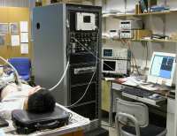
The Laboratory consists of four major sections: 1) advanced computing and electronic system testing facility, 2) ultrasound and optical experiment, 3) electronic circuit development, and 4) mechanical machine shop. The computing facility consists of more than 10 workstations, most of them are 3GHz Pentium IV with PCI Express 16 bus running both Linux and Windows operating systems, Sun Sparc and UltraSparc workstations, and many state-of-the-art computer peripherals. The electronic shop is equipped with many advanced instruments such as 200 MHz multichannel Tektronix Logic Analyzer and 5Hz-500MHz broadband HP Network Analyzer. The Ultrasound room has a dedicated ultrasound scanning and high-speed digitizing system (100MHz at 12 bit) with custom software developed in the lab for ultrasound imaging and Doppler imaging experiments. The lab has also a commercial Acuson 128 XP10 clinical ultrasound imaging system. Facilities for ultrasound biological and chemical experiments are also available in the Ultrasound room. The machine shop has multiple machines including a high precision milling machine and a lathe for hardware constructions. A heavy optical table floating in the compressed air provides an ideal platform for optical imaging and other high-resolution imaging in the cellular level (Lu, pdf 64a). (Please click on images to enlarge!)
The NIH funding as well as the research achievements and expertise of the personnel in the lab have made the Ultrasound Laboratory at the University of Toledo one of the most advanced research facilities in the field of medical ultrasonic imaging.
|
|
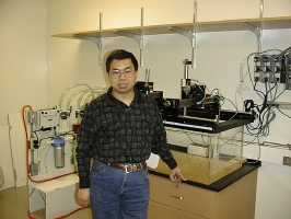
Fig. The front view of the ultrasound lab (Lu, pdf 64a).
|
|
|
|
|
|
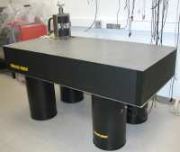
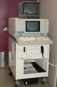
Fig. These pictures show an ultrasound table-top scanner (left and middle left), a corner of one of the rooms of the ultrasound lab (middle), an air-floating optical table and magnetic source (middle right), and a commercial Acuson 128/XP10 ultrasound imaging system (right) in Ultrasound Lab (Lu, pdf 64a).
|
|
|
|
Fig. In vivo experiment with a commercial Acuson 128 XP/10 ultrasound imaging system. Cardiac experiment (left), artery experiment (middle), and kidney experiment (right) (Lu et al, pdf 71 (Multimedia-zipped), Lu et al, pdf 64, and Lu, pdf 64a).
|
|
|
|
Fig. In vivo experiment with the high frame rate imaging system designed and constructed in the ultrasound lab (details of the high frame rate imaging system are given below). Cardiac experiment (left), artery experiment (middle), and kidney experiment (right) (Lu et al, pdf 71 (Multimedia-zipped), Lu et al, pdf 64, and Lu, pdf 64a).
Ultrasound and Optical Research Projects
Our Current Research Interests Are Summarized as Follows:
X Waves (see in "Search and Discovery" column of Physics Today, v.57, n.10, pp.25-26, October, 2004):
X waves were discovered in 1991 by Dr. Jian-yu Lu (Lu et al., pdf 9, Lu et al., pdf 11, and Lu et al., pdf 12) when he worked in Dr. James F. Greenleaf's lab at Mayo Clinic and were studied extensively by many other investigators (see partial list of dozens of relevant papers found before September 25, 2005 in well-known American Physical Society (APS) journals such as "Physical Review Letters"). X waves are one type of limited-diffraction beams where "limited-diffraction" means all practical beams will eventually diffract (the term "limited-diffraction beams" (Lu et al., pdf 20) was used to avoid the controversy of the terminology "nondiffracting beams" given by J. Durnin et al when they studied the Bessel beam (Durnin)). X waves are broadband (containing multiple frequencies) and, in theory, can propagate to an infinite distance without spreading (infinite large depth of field). In practice, these waves have a large depth of field even produced with finite aperture and energy. In addition, X waves of different orders or Axicon angles are orthogonal (Salo et al.) to each other and thus they can be used as basis functions to construct new limited-diffraction beams or any physically realizable waves in a way similar to the sine and cosine functions used in the Fourier Transform (Lu, pdf 31, Lu et al., pdf 52). X waves or other limited-diffraction beams can also be produced from any solutions to the wave equation by a Lorentz type of transformation that is the result of Einstein's Special Theory of Relativity (Lu et al., pdf 29). This means that one can obtain electromagnetic X waves from a different inertial reference frames in vacuum. Because of these properties of X waves, they are studied by many research groups in the world to produce laser X wave beams and are applied to various areas such as medical imaging (Lu et al., pdf 21) and high-speed optical communications (Lu et al., pdf 45). The group and phase velocity of theoretical X waves are identical and are greater than the speed of sound in a medium or speed of light in vacuum (superluminal). This is of interest to some physicists (Recami, Saari, Chatzipetros, and Wang, etc.) around the world. Two papers (Lu et al., pdf 11 and Lu et al., pdf 12) published in the IEEE (Institute of Electrical and Electronics Engineers) Transactions on Ultrasonics, Ferroelectrics, and Frequency Control (UFFC) related to the discovery of X waves were awarded by the IEEE UFFC Society in 1993. A recent review of the subject and a further development of X wave theory for Schrodinger and Klein-Gordon Equations with an extensive references (185) can be found in Lu, pdf 69a. (See PDF-Publications for details.) (Please click the photo for details!)

![]() (click image above to enlarge)
(click image above to enlarge)
Recently, X waves have been applied to different areas of physics including ultra-cold Bose Gas, nonlinear optics, photonic crystals, femtosecond laser pulses, and other areas. A long list of some of the developments based on X waves and related topics can be found in the well-known physical journals such as "Physical Review Letters", "Physical Review A (Atomic, molecular, and optical physics)", "Physical Review B (Condensed Matter and Materials Physics)", and "Physical Review E (Statistical, Nonlinear, and Soft Matter Physics)" from the American Physical Society. Click on the link for a partial list of 8 Physical Review Letters, 1 Physical Review B, and 31 Physical Review E papers found before September 25, 2005.
In summary, X waves are broadband (containing multiple frequencies) and superluminal (speed of the waves is larger than the speed of light in vacuum or speed of sound in homogeneous media) solutions to the isotropic/homogeneous wave equation. Theoretically, X waves can propagate to infinite distance in a highly focused wave packet (in both time and space domains) without spreading.
More details on X waves: An X wave transform (Lu et al., pdf 52); Application in high frame rate imaging theory (Lu, pdf 39); Application in high frame rate imaging experiment (Lu, pdf 40); X wave and Lorentz transform (Lu et al., pdf 29); X wave research review (Lu et al., pdf 21); First X wave theory (Lu et al., pdf 11); and First X wave experiment (Lu et al., pdf 12), etc. Some X wave links can be found by searching on web using, for example, Google, by typing in the phrases such as "X Waves", "Limited-Diffraction Beams", or "Nondiffracting Beams", etc. (use the quotes to indicate the phrases when search):
X Waves as Educational Materials: Two X wave papers (Lu et al., pdf 11 and Lu et al., pdf 12) have been used as ultrasound educational materials on the IEEE UFFC website under the title "Outstanding Paper Awards":
High Frame Rate Ultrasound Imaging System (one of the predictions for the 21st Century ultrasonics in: Glen Wade, Ultrasonics, vol.38, pp.1-5 (2000), and "an intriguing development in high-speed imaging" in Peter N. T. Wells, Physics in Medicine and Biology, vol. 51, no. 13, pp. R83�R98 (2006)):
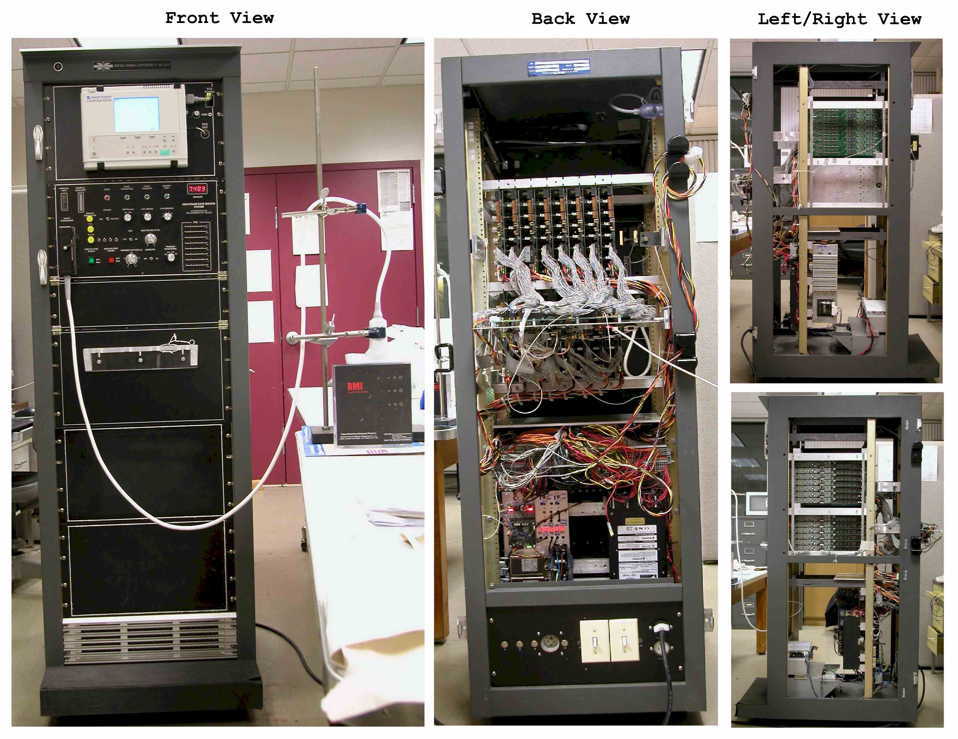
We have developed a high frame rate imaging method (Lu, pdf 39 and Lu, pdf 40) based on the X wave (or limited-diffraction beam) theory. Recently, the high frame rate imaging method has been extended to include explicitly multiple steered plane wave (Lu, pdf 39, Lu, pdf 40, Lu et al, abs 23, and Lu, abs 19) and limited-diffraction array beam (Lu, pdf 37, Lu, pdf 43, and Lu, pdf 34) transmissions (Lu et al, pdf 71 (Multimedia-zipped), Cheng and Lu, pdf 67, and Cheng and Lu, pdf 70). To further test the high frame rate imaging methods, we have designed and constructed a prototype high frame rate imaging system (Lu et al, pdf 71 (Multimedia-zipped), Lu et al, pdf 64, and Lu, pdf 64a). (The design of the system started in fall, 1997, and a design that was based on the surface mount technology (SMT) components and field programmable gate arrays (FPGAs) started late 1999. Due to the fast pace of the electronic technologies, our system design was modified from time to time to take the advantages. Although it takes time to develop such a complicated system ourselves, unlike a commercial system, it provides a long-term benefit and flexibility for us to expend and adapt to various research projects using gained experiences and established infrastructure.) The ultimate goal is to reconstruct 3D ultrasonic images at a rate of about a few thousand volumes per second with simple electronics. This will reduce dramatically motion artifacts of moving objects such as the heart, especially, the fetus heart where a stable electrocardiograph (ECG) signal is difficult to obtain to synchronize the data acquisition. In addition, the ultrahigh frame rate imaging could make ultrasound functional imaging possible. The development of the system involves the construction of high-speed analog (a few MHz) and digital (tens of MHz) circuits. We have developed analog circuits that have a wide bandwidth and low noise to obtain signals returned from deep tissues (typically around 20 cm) for a high quality image reconstruction. The analog circuits are also capable of tissue nonlinear (harmonic) ultrasound imaging. The digital circuits and system control were developed based on FPGAs. Multi-layer printed circuit boards (PCBs) and mechanical and electrical interconnections were carefully designed and constructed. The hardware of the entire system is so complicated that the students and postdocs in the lab were not confident that such a system could have ever been made by ourselves. This made the tasks more challenging. To overcome the difficulties, the lab director, Dr. Jian-yu Lu, has to manage the details of the project and design the final version of the entire circuits, select appropriate electrical and mechanical components, and place the components on PCBs using a layout software so that students could route the PCBs properly to minimize high frequency RFI (radio frequency interference) and EMI (electromagnetic interference). Some comments on the High frame rate imaging method can be found in a recent review paper, Paul Carson and Aaron Fenster, "Anniversary Paper: Evolution of ultrasound physics and the role of medical physicists and the AAPM and its journal in that evolution," Medical Physics, vol.36, no. 2, February 2009, pp. 411-428.
Photos, movies, and animations showing the constructed high frame rate imaging system (Lu et al, pdf 71 (Multimedia-zipped), Lu et al, pdf 64, and Lu, pdf 64a). (Please click on images to enlarge or see movies!)
|
|
||||
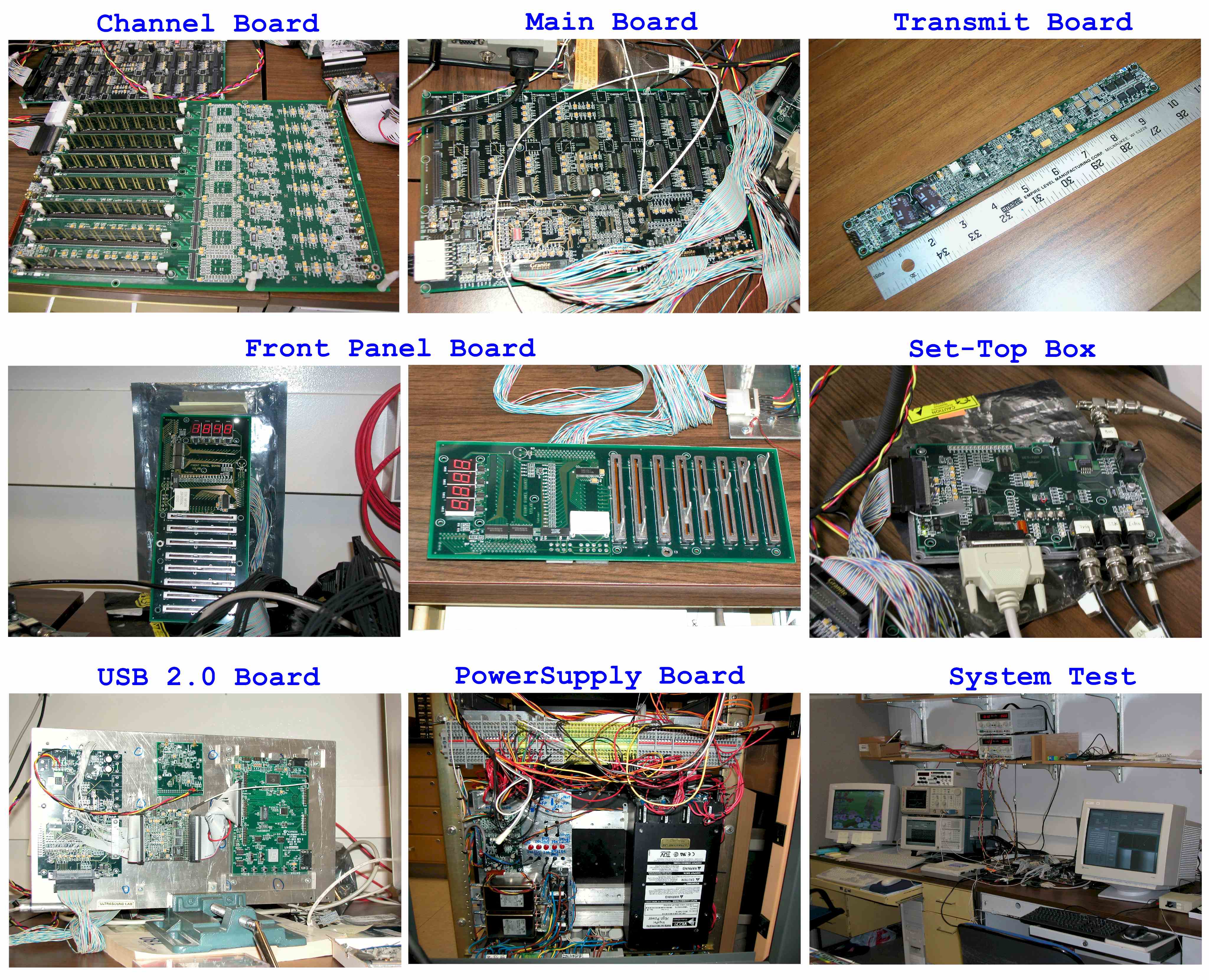
Fig. Development of High Frame Rate Ultrasound Imaging System - On the left, it shows an eight-layer printed circuit board (PCB) used primarily for multi-channel ultrasound signal reception and storage. The board was designed in the Ultrasound Lab at the University of Toledo, led by Dr. Jian-yu Lu. It is one of the many PCBs designed for a high frame rate medical ultrasound imaging system. The system consists of 128 linear, high-voltage, and 12-bit arbitrary waveform generators (transmitter) for synchronized generation of ultrasound signals or for other research purposes. The rest four panels are movies or animations from the system design to test. Detailed (longer) movies can be viewed by clicking on the links below the figures "Click Here for a Longer Video".
The following figures show the details of the high frame rate imaging system. Radio frequency (RF) signals acquired with the system are used to reconstruct images (Lu et al, pdf 71 (Multimedia-zipped), Lu et al, pdf 64, and Lu, pdf 64a). (Please click on images to enlarge!)
|
|
|
|
|
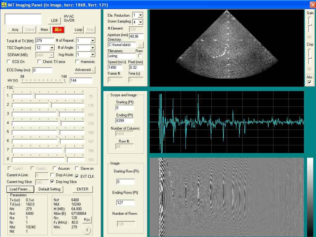
Fig. High Frame Imaging System (HFR) and Reconstructed Images: Left: system overview; Middle Left: system circuit boards development and test; Middle Right: use of the imaging system with a commercial tissue-mimicking phantom; Right: image reconstructed using data acquired with the completed imaging system. The movie shows the operations of the imaging system for: (1) radio frequency (RF) data acquisition, data display, and image reconstruction, (2) sequential transmission of one element at a time and reception with all channels, (3) data acquisition, data display, and image reconstruction with the dynamic receive focusing method from 279 transmissions for a wire phantom.
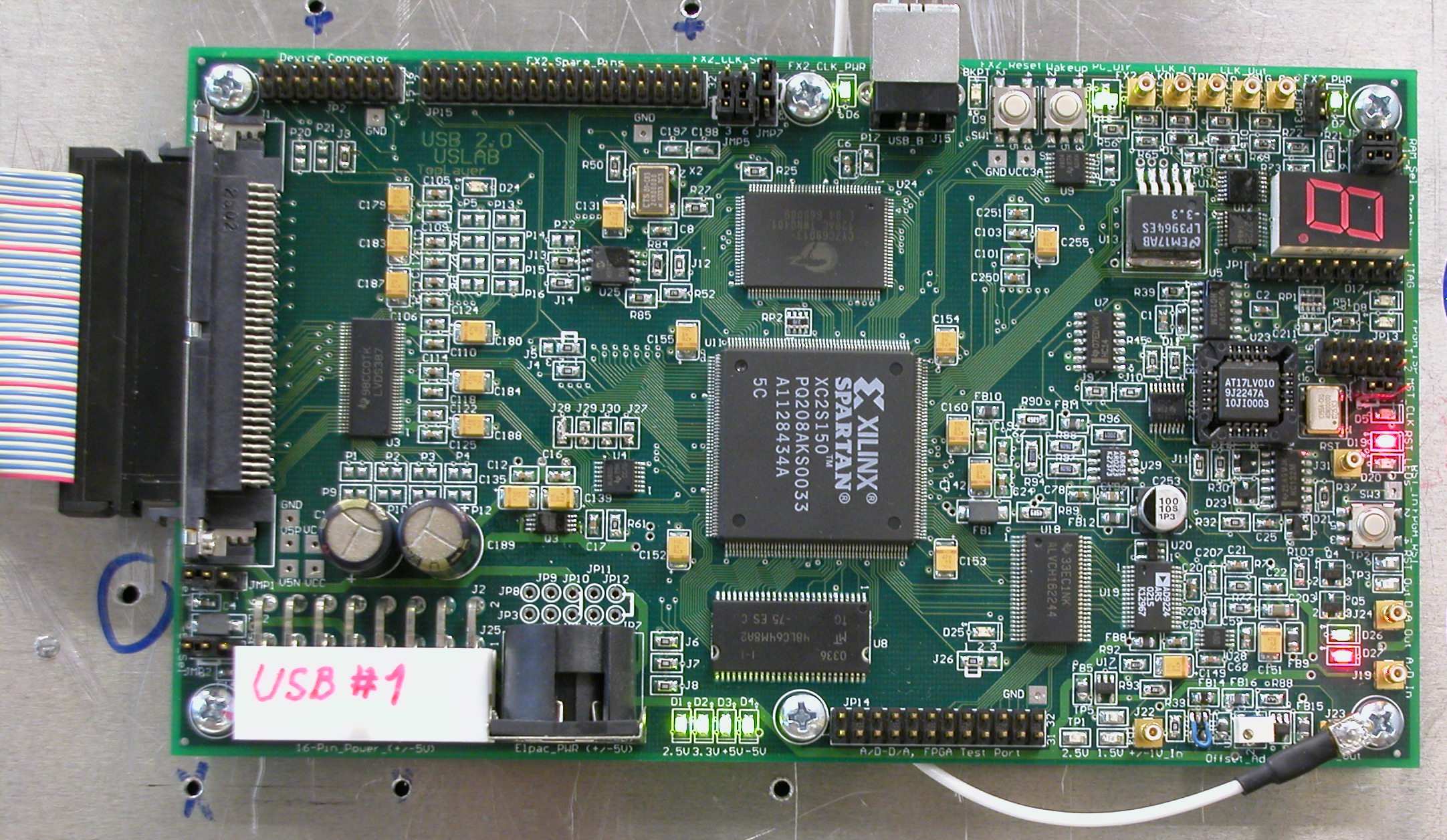
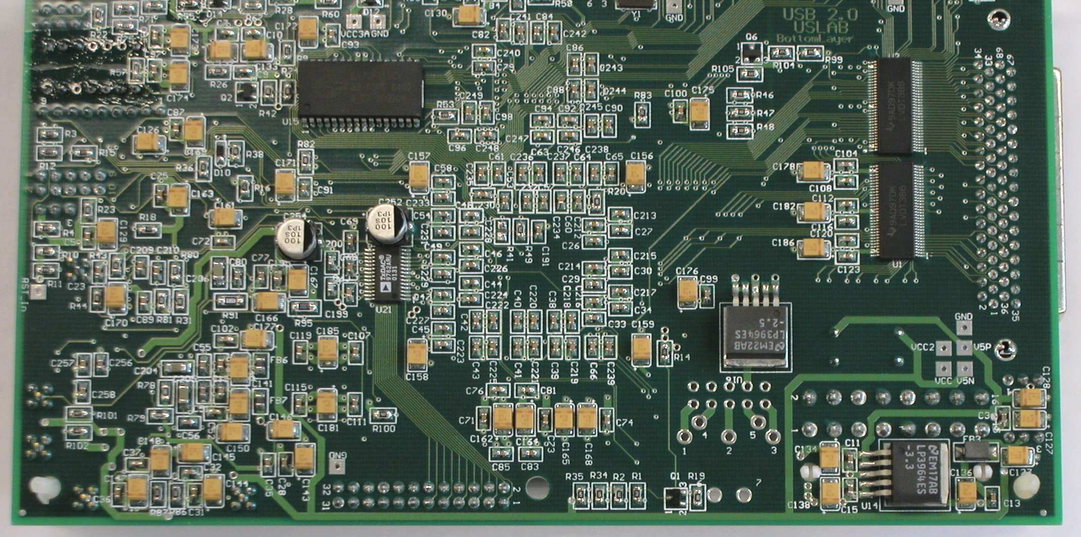
The following figures show an integrated USB 2.0 Board for communication between the high frame rate imaging system and a personal computer. It replaced four temporary USB 2.0 boards shown above (Lu et al, pdf 71 (Multimedia-zipped), Lu et al, pdf 64, and Lu, pdf 64a). (Please click on images to enlarge!)
|
|
|
|
Fig. An integrated USB 2.0 board establishes a control and data links between the high frame rate imaging system (with up to 65 Giga Bytes of in-system memory) and a personal computer. In addition, this board is capable of independent 12-bit/40MHz A/D data acquisition and D/A for linear control with a memory depth of 64 Mega Bytes on board. The board can be flexibly triggered and synchronized with outside equipment. Left: Top side view of the USB board; Middle: Bottom view of the USB board; and Right: A Converter made to allow all Acuson probes to be used with the high frame rate imaging system.
Some more RF data and reconstructed images obtained with the high frame rate imaging system (Lu et al, pdf 71 (Multimedia-zipped), Lu et al, pdf 64, and Lu, pdf 64a). (Please click on images to enlarge!)
|
|
|
|
|
|
|
|
|
Fig. Top row: Rubber-based ATS539 tissue-mimicking phantom and the images of the phantom reconstructed with the high frame rate method from 5 angles using data obtained with the high frame rate imaging system (with only 5 transmissions and about 160 us for each transmission - 1250 frames/s). Bottom row: Images reconstructed with conventional delay-and-sum (dynamic focusing) method (279 transmissions with equal sine(theta) angular spacing is used, where theta is the steering angle - 22 frames/s). The transmission focus is at 7 cm from the apex and the image depth is 12 cm.
The following images are results of extended high frame rate imaging methods (Lu et al, pdf 71 (Multimedia-zipped), Cheng and Lu, pdf 67, and Cheng and Lu, pdf 70). Please see "PDF Publications" link on the left frame for details.
Computer simulations (Lu et al, pdf 71 (Multimedia-zipped), Cheng and Lu, pdf 67, and Cheng and Lu, pdf 70). (Please click on images to enlarge!)
|
|
|
|
|
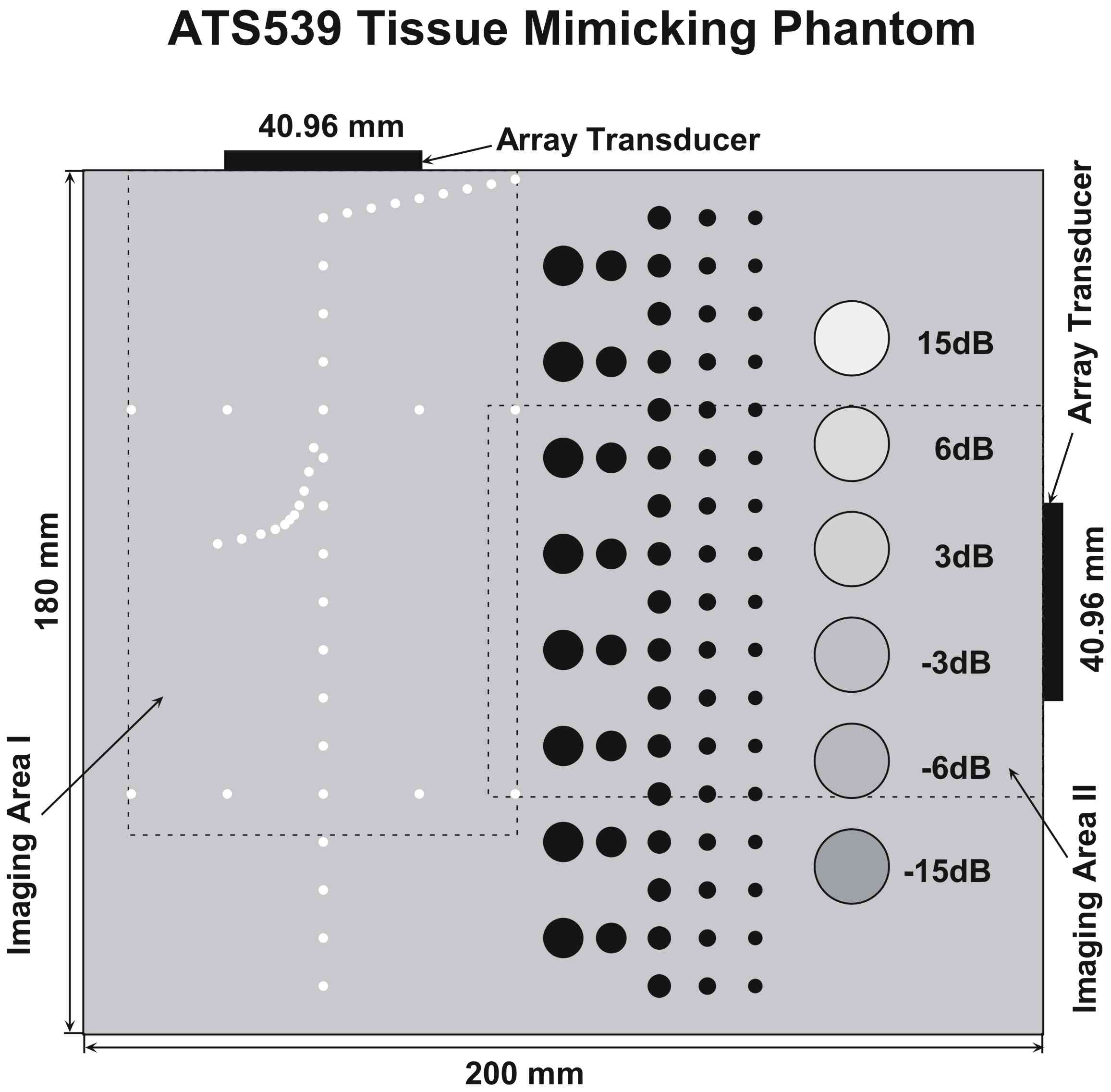
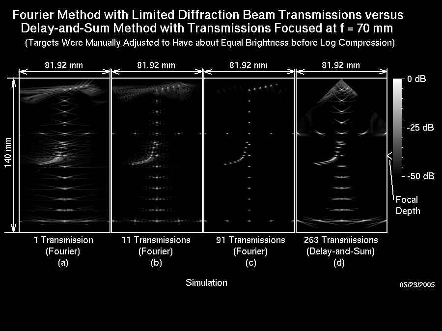
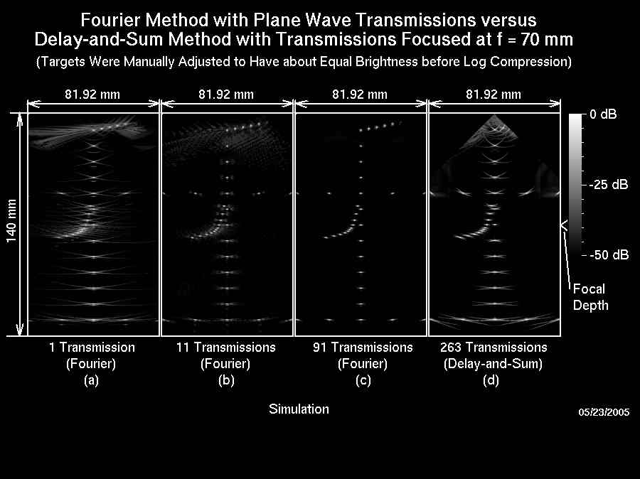
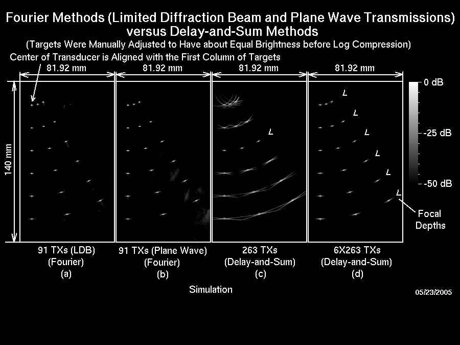
Fig. Left: Structure and imaging areas of an ATS539 multipurpose tissue-mimicking phantom. Middle Left: Simulated images according to the imaging Area I of the ATS539 phantom. Images are reconstructed with limited-diffraction array beam transmissions. Images are log-compressed at 50 dB. The transducer has 128 elements, 40.96 mm aperture, 0.32 mm pitch, 3.5 MHz center frequency, and 58% -6dB pulse-echo bandwidth. The area of each image panel is 81.92 x 140 mm. Images are obtained with (a) 1 (up to 5500 frames/s with 1540 m/s speed of sound), (b) 11 (up to 500 frames/s), and (c) 91 (up to 60 frames/s) transmissions, respectively. (d) Result obtained with the conventional delay-and-sum (D&S) method with a fixed transmission focal depth of 70 mm, a dynamically focused reception, and with 263 transmissions (up to 21 frames/s). Middle Right: The same as the Middle Left image except that steered plane waves are used in transmissions, instead of limited-diffraction array beams. Right: Simulated images for 18 point scatterers on three lines with 15 degrees between the lines. Six point scatterers are distributed evenly over each line with 20 mm spacing. The log compression, image panel size, and the parameters of the transducer are the same as those in the Middle Left image. Image reconstructed with: (a) limited-diffraction array beam transmissions (91 transmissions up to 59 frames/s); (b) steered plane wave transmissions; (c) D&S method with a fixed focal depth at 60 mm and a dynamically focused reception (263 transmissions up to 20 frames/s); and (d) D&S method with a dynamically focused transmission synthesized using a montage process and a dynamically focused reception.
In vitro experiment of ATS539 tissue mimicking phantom (Lu et al, pdf 71 (Multimedia-zipped), Cheng and Lu, pdf 67, and Cheng and Lu, pdf 70). (Please click on images to enlarge!)
|
|
|
|
|
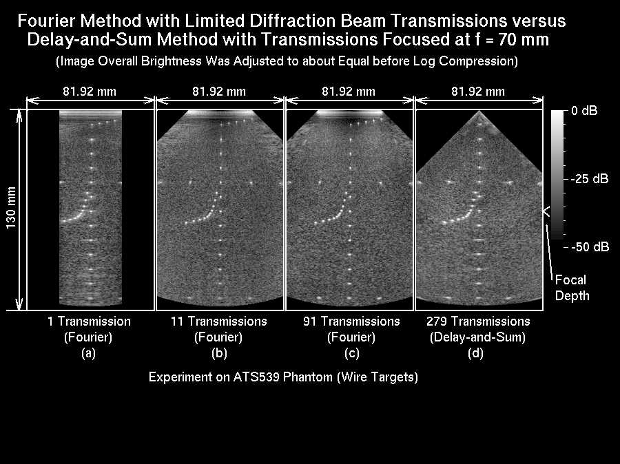
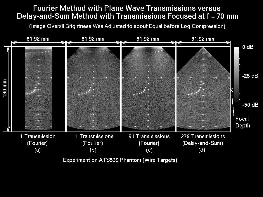
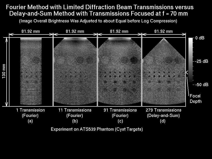
Fig. Left: The same as the Middle Left image in the computer simulations above except that these are experiment results from a real ATS539 phantom on imaging Area I (see the Left figure in the computer simulations above) using a real transducer. The speed of sound of the phantom is 1450 m/s and the -6dB pulse-echo bandwidth of the transducer is about 50% of the center frequency. Middle Left: The same as the Left image except that steered plane waves are used in transmissions instead of limited-diffraction array beams. Middle Right: The same as the Left image except that the imaging Area II of cystic objects of the ATS539 phantom (see the Left figure in the computer simulations above) is used in the experiments. Right: The same as the Middle Right image except that steered plane waves are used in transmissions instead of limited-diffraction array beams.
In vitro experiment of a wire phantom and In vivo experiments of a human kidney and heart (Lu et al, pdf 71 (Multimedia-zipped), Cheng and Lu, pdf 67, and Cheng and Lu, pdf 70). (Please click on images to enlarge!)
|
|
|
|
|
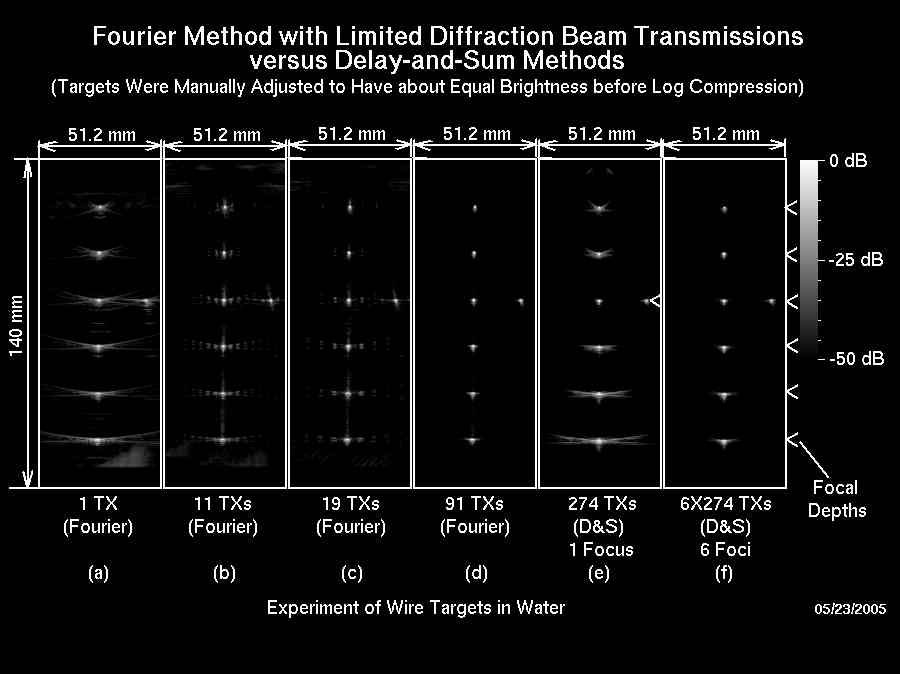
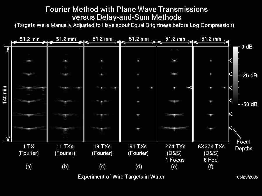
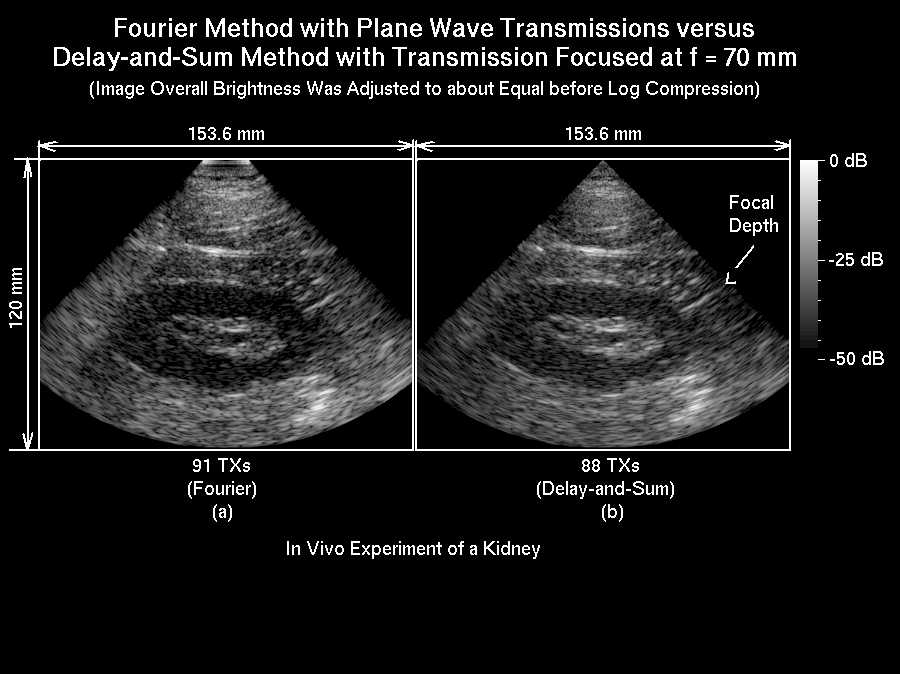
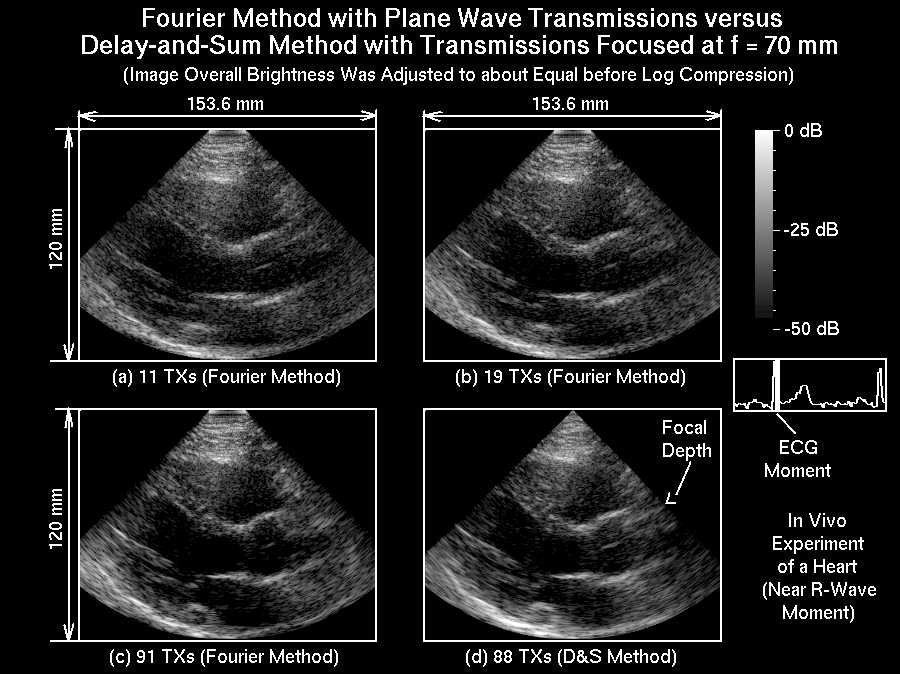
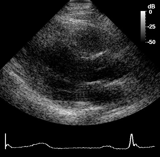
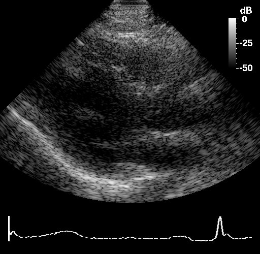
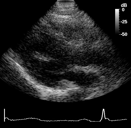
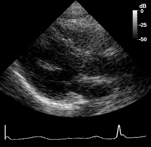
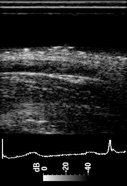
Fig. Left: Experiment results of a wire phantom in water. Images are reconstructed with limited-diffraction array beam transmissions. There are 7 wires in total with 6 wires in a line and one wire on the third row 20 mm to the right of the line. The image panel size is 51.2 x 140 mm. The 6 wires are evenly distributed with 20 mm spacing. The log compression and the parameters of the transducer are the same as those in the Middle Left image of the computer simulations above, except that the -6dB pulse-echo bandwidth of the transducer is about 50%, instead of 58%, of the center frequency. Images are obtained with (a) 1 (up to 5277 frames/s, with 1477.56 ms speed of sound), (b) 11 (up to 479 frames/s), (c) 19 (up to 278 frames/s), and (d) 91 (up to 58 frames/s) transmissions, respectively. (e) Result obtained with the D&S method with a fixed transmission focal depth of 60 mm, a dynamically focused reception, and with 274 transmissions (up to 19 frames/s); and (f) Result of the D&S method with a dynamically focused transmission synthesized with a montage process and a dynamically focused reception. Middle Left: The same as the Left image except that steered plane waves are used in transmissions instead of limited-diffraction array beams. Middle Right: In vivo experiments of a right kidney of a volunteer. An Acuson V2 probe of 128 element, 2.5 MHz center frequency, 19.2 mm aperture, 0.15 mm pitch, and 14 mm elevation with 68 mm elevation focal depth is used. The depth of images is 120 mm. Data are acquired at the highest frame rate that the HFR system is allowed for the depth (187 us between transmissions or 5348 frames/s for a speed of sound of 1540 m/s). (a) Image reconstructed with 91 steered plane wave transmissions (59 frames/s). (b) Image reconstructed with the D&S method with a fixed focal depth of 70 mm, a dynamically focused reception, and 88 transmissions (61 frames/s). Right: In vivo experiments of the heart of a volunteer. The transducer parameters, the depth of images, and the settings of the HFR imaging system are the same as those in the Middle Right image. Data acquisition of the heart is triggered and synchronized by an electrocardiograph (ECG) signal to get images at the desired heart cycle moments (see the ECG display on the right hand side panel). Image reconstructed with (a) 11 (486 frames/s), (b) 19 (281 frames/s), and (c) 91 (59 frames/s) steered plane wave transmissions. (d) Image reconstructed with the D&S method with a fixed focal depth of 70 mm, a dynamically focused reception, and 88 transmissions (61 frames/s).
In vivo heart images reconstructed with the limited-diffraction array beams with square-wave aperture weightings (Lu et al, pdf 71 (Multimedia-zipped)). (Please click on images to enlarge!)
|
|
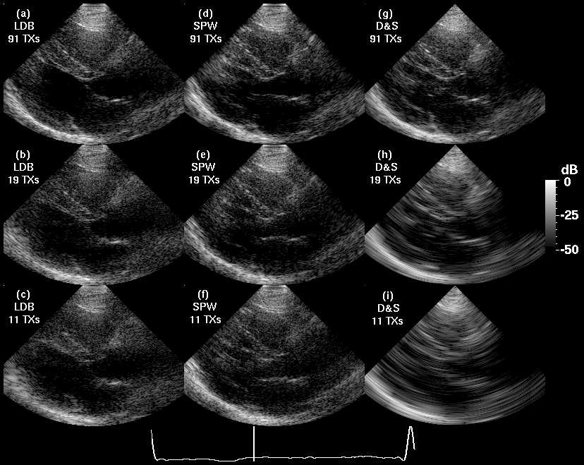
Fig. In vivo heart images of a volunteer for comparison between limited-diffraction array beam imaging with square-wave aperture weightings (Panels (a), (b), and (c)) and other imaging methods (steered plane waves in Panels (c), (d), and (e), and D&S method with a dynamically focused reception in Panels (f), (g), and (h)). Panels in the top, middle, and bottom rows correspond to the conditions of 91 (59 frame/s with 187 us between transmissions), 19 (281 frames/s), and 11 (486 frames/s) transmissions to reconstruct a frame of image, respectively. Images are log-compressed with a dynamic range of 50 dB. The electrocardiogram (ECG) at the bottom of the figure is obtained from the same volunteer. The vertical bar in the ECG indicates the starting moment when the series of images in this figure are acquired (this is roughly the moment of a rapid ventricular filling that pushes the mitral valve open quickly). An animation that loops through an entire heart cycle is shown in the multimedia animation file (![]() ).
).
In vivo images of heart and blood vessel reconstructed at different frame rates and with different imaging methods (Lu et al, pdf 71 (Multimedia-zipped)). (Please click on images to enlarge!)
|
|
|
|
|
|
|
|
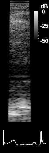
Fig. In vivo heart and artery images of a volunteer of a heart rate of about 70 cycles per minute (see "Introduction to Ultrasound Laboratory" above for experiment setups). Top Row: Heart images reconstructed with a broadband transducer of 128 elements, 2.5MHz center frequency, 19.2 mm aperture, 14 mm in elevation, and 68 mm elevation focal distance. (1a) Images reconstructed at 5348 frames/s with the extended HFR imaging method (display frame rate = 60 frames per heart cycle and image size = 160x500 or 48mm x 150mm); (2a) Images reconstructed at 486 frames/s with the extended HFR imaging method (display frame rate = 59 frames per heart cycle and image size = 512x500 or 153.6mm x 150mm); (3a) Images reconstructed at 281 frames/s with the extended HFR imaging method (display frame rate = 60 frames per heart cycle and image size = 512x500 or 153.6mm x 150mm); (4a) Images reconstructed at 59 frames/s with the extended HFR imaging method (display frame rate = 47 frames per heart cycle and image size = 512x500 or 153.6mm x 150mm); (5a) Images reconstructed at 61 frames/s with conventional delay-and-sum method with a transmission focal distance at 7cm (display frame rate = 49 frames per heart cycle and image size = 585x500 or 175mm x 150mm). Bottom Row: Images of a blood vessel (artery in right arm) reconstructed with a broadband transducer of 128 elements, 5MHz center frequency, 38.4 mm aperture, 5 mm in elevation, and 20 mm elevation focal distance. (1b) Images reconstructed at 12500 frames/s with the extended HFR imaging method (display frame rate = 44 frames per heart cycle and image size = 256x375 or 38.4mm x 56.25mm).
Software Development for Data Transfer from the High Frame Rate Imaging System to a PC:
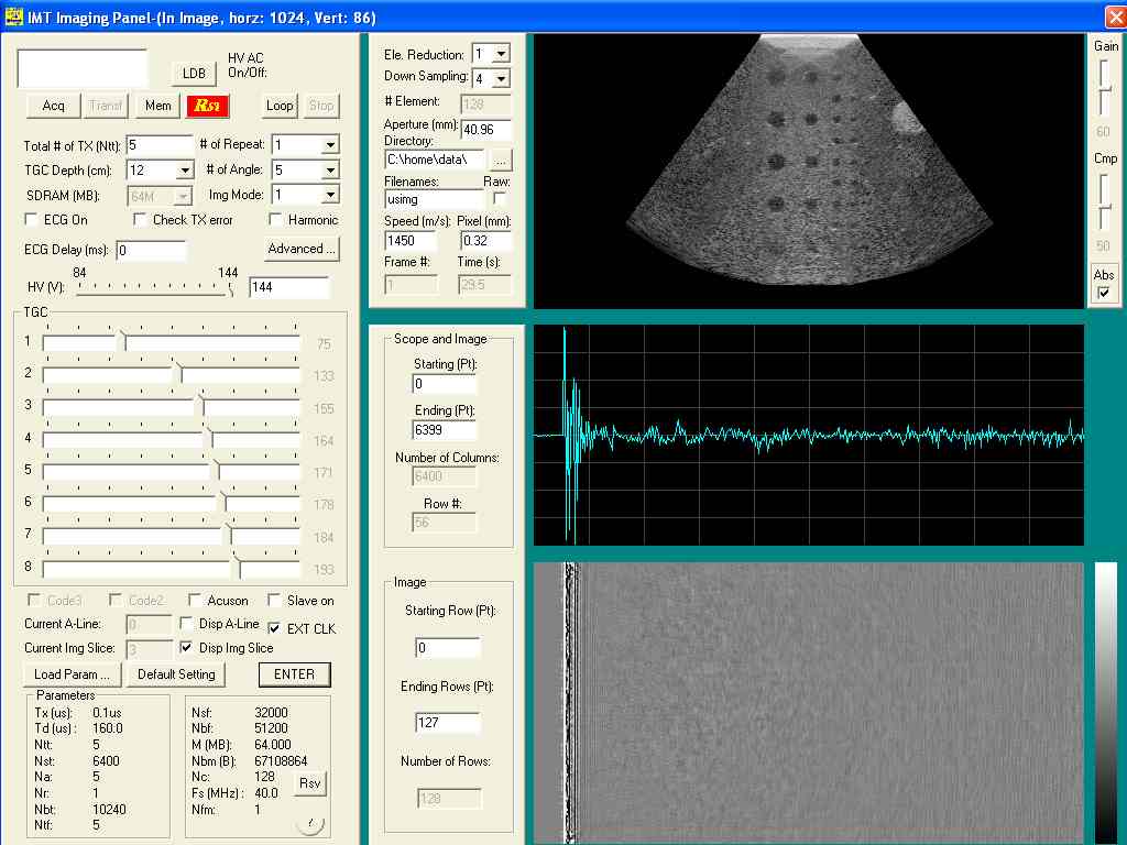
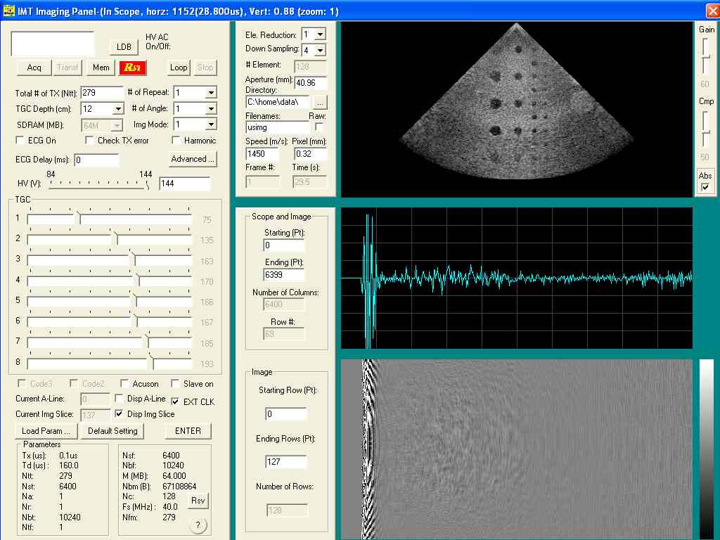
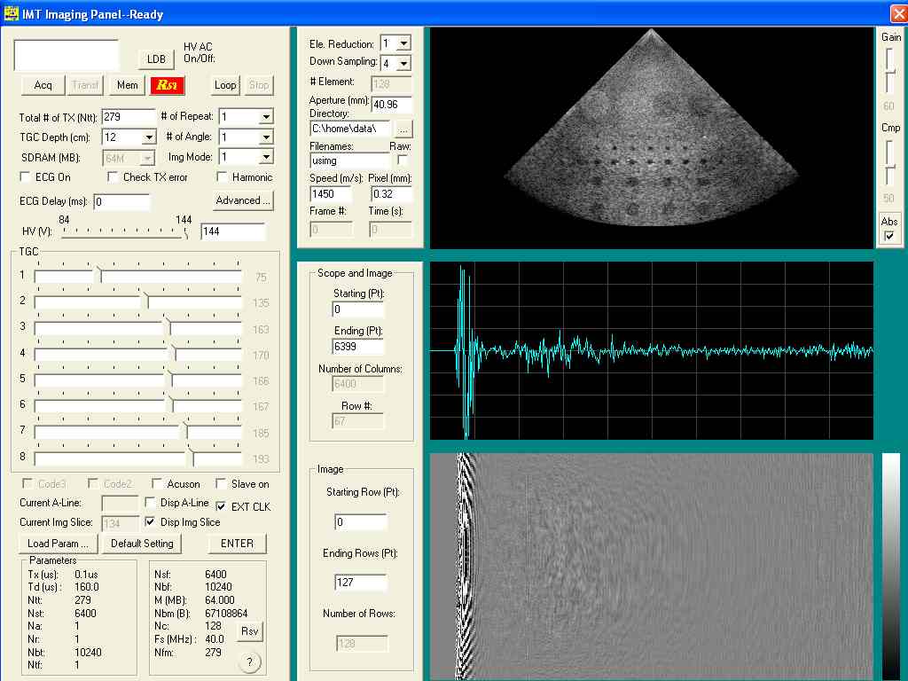
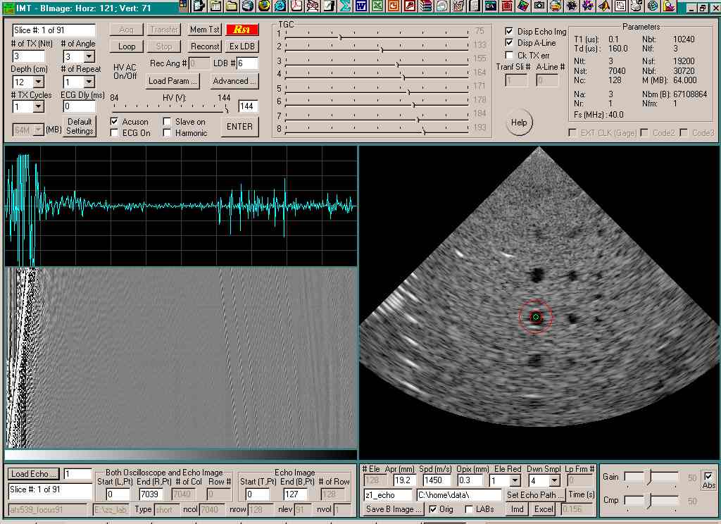
To transfer data from the high frame rate imaging system to a PC for image reconstruction, an application program (called IMT) in Windows Xp has been developed with the Microsoft Visual C++. The program can transfer data via either USB 2.0 or a 100MB/s 12-bit Gage card. An example of the IMT program is shown below:
|
|
Fig. An example of IMT program showing an ATS539 tissue-mimicking phantom image reconstructed with the high frame rate method from 5 angles using data obtained with the high frame rate imaging system (with only 5 transmissions and about 160 us for each transmission - 1250 frames/s).
Software Development for Image Reconstruction Labs (IRLAB) for Undergraduate Required Lab Course and Improvement of IMT (December 11, 2011):
A software called IRLAB (image reconstruction labs) for an undergraduate required lab course has been developed with Microsoft Visual C++. This program combines an improved version of IMT software above to allow students to perform signal processing, image processing, and image reconstruction of ultrasound images:
|
|
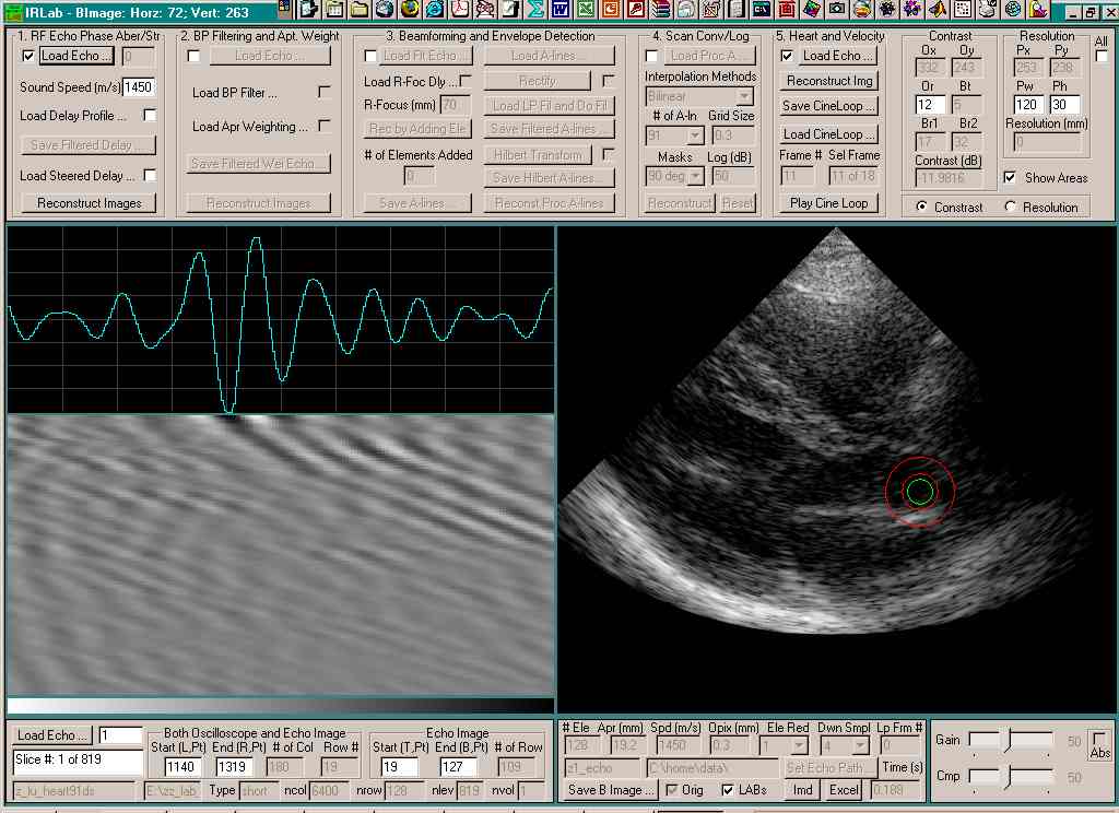
|
Fig. IRLAB software is used to display RF echo signals and corresponding reconstructed beating heart images (see image on the left). An image of ATS539 phanton and its corresponding RF echo signals are shown with an improved IMT software (see image on the right).
Software Development for Image Display and Manipulation:
An image display and layout software (IMD) has been developed with the Gimp Tool Kits (GTK). This software can be used to transfer data from the high frame rate imaging system to a personal computer (PC) via extended parallel port (EPP) (up to 5 MB/s) in Linux operating system. The program was developed with GTK++ (Gimp Took Kits, http://www.gtk.org/) and the GUI (graphical user interface) was developed with GLADE (http://glade.gnome.org/). A Linux driver with multi-thread support has been developed for the EPP parallel port data transfer. The software is also used to reconstruct images with the high frame rate method (Lu, pdf 39 and Lu, pdf 40), display reconstructed images, and do image analysis with line plots or image manipulations. It is also used to produce images for journal publications. The software has been ported to Windows Xp system.
FPGA Programs for the High Frame Rate Imaging System:
Field programmable gate array (FPGA) programs that are used to control the hardware of the high frame rate imaging system were developed. They are used to work with the image data transfer (IMT) program to transfer data from the high frame rate imaging system to a PC or to send control and beamforming commands to the imaging system from the PC.
____________________________________________________________________
Study of Bessel Beams for Medical Imaging:
Conventional beams suffer from diffraction spreading when they propagate in space. In 1941, J. A. Stratton discovered a beam called Undistorted Progressive Waves (UPW) and described this discovery in his book, "Electromagnetic Theory", on page 356. This wave can propagate to an infinite distance without spreading. Forty-six years later, in 1987, Durnin investigated this wave with an optical experiment and called the UPW Bessel beam because the beam has a transverse profile of a Bessel function. Durnin also called the Bessel beam "nondiffracting beam" or "diffraction-free beam". Because Durnin's terminologies are controversial in scientific community and all practical beams are subject to diffraction spreading eventually, we have used the term "limited-diffraction beams". We are the first to produce Bessel beams with an acoustic annular array device and apply them to medical ultrasonic imaging. (See the papers at the beginning of 1990s (Lu et al., pdf 6 and Lu et al., pdf 7) and a patent (Lu et al., pdf 10)). Because limited-diffraction beams can propagate to a large distance without spreading, they have applications in medical imaging (Lu et al., pdf 6), tissue property identification (Lu et al., pdf 8), nondestructive evaluation (NDE) of materials (Lu et al., pdf 18), and other areas such as physics and optics. Our lab is continuing the research and applications of these novel beams. (See PDF-Publications for details.) (Please click the photo for details!)
|
|
|
|
Computation of Ultrasound or Optical Beams (Waves) with the Fourier-Bessel Decomposition of Transducer Aperture Weighting Functions and Tuning of Wave Fields:
The Fourier-Bessel method for computation of ultrasound or optical beams (waves) have been studied. The method can be used to calculate Bessel field or any other fields produced with an array of axial symmetry. The method also helps engineers to design a desired beam pattern by calculating the transducer aperture weighting function (tuning) (Fox et al, pdf 62). The method have been extended to multi-frequency arrays (Fox et al, pdf 63). Extension of the method to 2D arrays have also been investigated (Jian-yu Lu and Jiqi Cheng, "Efficient computation of field of 2D array with limited-diffraction array beams," Journal of Acoustical Society of America, vol. 109, no. 5, pt. 2, pp. 2397-2398, 2001 (abstract)). (See PDF-Publications for details.)
Study of 2D Array Transducers and Fast Beam Computation with Limited-Diffraction Array Beams:
Limited-diffraction array beams were studied by Dr. Lu in 1997 (Lu, pdf 34). Production of limited-diffraction beams with a 2D array transducer was studied previously (Lu et al, pdf 24, pdf 16). Recently, the array beam theory was applied to a fast computation of the field of 2D array transducers (Lu et al, pdf 68). This is important because it makes simulations of many ultrasound imaging methods using 2D arrays possible. (See PDF-Publications for details.)
Ultrasonic Imaging of a Large Depth of Field:
Ultrasonic imaging with limited-diffraction beams has a large depth of field (Lu et al., pdf 14). This overcomes the problems of focused beams. For example, with an optical camera, clear pictures can only be obtained when objects are at the focal distance. This is because the camera has a short depth of field. However, a large depth of field in optical imaging is desirable. In medical ultrasonic imaging, a large depth of field is also desirable. A large depth of field may make clear images over an entire region of interest in human body. In addition, limited-diffraction beams can also be applied to improve Doppler blood flow imaging (Lu et al., pdf 25 and Lu, pdf 37). (See PDF-Publications for details.)
Sidelobe Reduction with Bowtie or Higher-Order Limited-Diffraction Beams:
Sidelobes in medical ultrasonic imaging may reduce image contrast. Bowtie beams (Lu, pdf 30, Lu, pdf 33, and Lu et al., pdf 32) have an unsymmetrical sidelobe distribution around the beam propagation axis. By transmitting and receiving signals with and without a 90 degree rotation of the beam pattern around the beam axis, respectively, the sidelobes in transmit can cancel those in the receive. This may produce a low sidelobe image while maintaining a large depth of field. A summation-subtraction method using higher-order limited-diffraction beams has also been studied for sidelobe reduction (Lu et al., pdf 20). It reduces sidelobes by subtracting sidelobes while maintaining the mainlobe of the beam. (See PDF-Publications for details.) (Please click the photo for details!)

![]() (click image above to enlarge)
(click image above to enlarge)
Nonlinear Imaging with Limited-Diffraction Beams:
We are studying limited-diffraction beams for nonlinear ultrasonic imaging (Ding and Lu, pdf 49 and Ding and Lu, pdf 50). Harmonics of the zeroth-order and higher-order limited-diffraction beams were studied both theoretically with the Khokhlov-Zaboloskaya-Kuznetsov (KZK) equations and experimentally. (See PDF-Publications for details.)
Optical Coherence Tomography (OCT) with Limited-Diffraction Beams:
Limited-diffraction beams are applied to the optical coherence tomography imaging system to increase the depth of field (Lu et al., pdf 59). The OCT system is used for skin cancer detection, in vivo pathological analysis, and intravascular imaging. A sidelobe reduction method developed for ultrasonic imaging is used to reduce the sidelobes and thus enhances the contrast of the limited-diffraction OCT (Lu et al., pdf 20). This work on OCT has been introduced in the review paper, A. F. Fercher, W. Drexler, C. K. Hitzenberger, and T. Lasser, "Optical coherence tomography - principles and applications," Reports on Progress in Physics, vol. 66, no. 2, 2003, p. 239-303, ISSN: 0034-4885. (See PDF-Publications for details.)
Laser Communications with Limited-Diffraction Beams:
Applications of limited-diffraction beams to laser optical communications were studied (Lu, pdf 42, Lu et al., pdf 45). With the new method, it is expected that the data rate can be increased by a few folds with existing communication bandwidth. (See PDF-Publications for details.)
Application Software for Multi-Axis and General-Purpose Ultrasound Scanner:
Application software for the flexible and general-purpose tabletop ultrasound scanner has been developed with Microsoft Visual C++. The software was designed for various experiments including imaging and Doppler experiments. A graphical user interface allows an easy and precise control of the 3D positioning system. The highest resolution of the positioning system is about 5 mm or 25000 steps/revolution or 200 nm/step.
Ultrasound Cleaning of Membranes for Drinking Water Treatment:
In collaboration with the Department of Chemical Engineering at the University of Toledo, we have applied the phased array technology that is widely used in medical imaging to clean membranes (microfiltration, ultrafiltration, and nanofiltration) for treatment of drinking water. In this application, low-powered ultrasound transducers can be used to achieve a high ultrasound intensity at focus to produce cavitations to clean the membranes. (Lu et al., pdf 78).
Novel Imaging Methods:
We are developing novel imaging methods for both biological organs and cells based on both new physics and mathematics.
Study of Fundamental Physics:
In addition to the engineering research, we are studying the fundamental physics phenomena for a better understanding of the world we live (new laws of physics) and for the applications of new physics (Lu, pdf 69 and Lu, pdf 69a).
Misc:
(1) Extended high frame rate imaging method has been further studied for the effects of object motions (pdf 66). (2) More study of limited-diffraction beams have been carried out to display the formation and propagations of these beams (pdf 15), modify X waves to increase depth of field (pdf 17), obtain pulse-echo images with X waves (pdf 35), produce real-time in vitro and in vivo images with these beams (pdf 19), compare sidelobes of these beams and localized waves (pdf 28), reduce sidelobes of these beams (pdf 51), design these beams of particular spatial properties (pdf 36), study the velocity of these beams in theory (pdf 38), reduce number of elements of transducer arrays for these beams (pdf 44, pdf 46), study the phase aberration (pdf 47) and noise (pdf 53) effects on the high frame rate imaging method, review the principle and application of these beams (pdf 48), apply these beams to Doppler blood flow imaging with storage correlation array (pdf 54) and steering (pdf 55), study ultrasound coded excitations with these beams to reduce sidelobes (pdf 57) and increase image frame rate (pdf 58), obtain high frame rate imaging with a cylindrical array (pdf 61), and connect between X waves and Fourier-Bessel analysis for circularly symmetric transducers (pdf 65). (3) Acoustic waves were studied to shorten pulse width to enhance image axial resolution (pdf 4). Wave propagations in 3D were also presented (pdf 5). Schlieren system was used to view the acoustic waves and reconstruct 3D images of the waves (pdf 27). (4) Non-destructive evaluation of transducers and arrays were performed with a high-resolution near-field scan technique with minimal diffraction effects (pdf 26). (5) Diffraction tomography is to reconstruct images from scattered or diffracted waves under weak scattering (or Born) approximation. This includes electromagnetic and ultrasound waves. (pdf 1, pdf 2, pdf 3). (6) Nonlinear properties of relaxor transducers were explored for the potential use as phase-insensitive detectors (pdf 13). (7) Volume of atherosclerotic plaques was determined with ultrasound (pdf 60). (8) Nano-scale studying of biomaterials was studied (pdf 26).
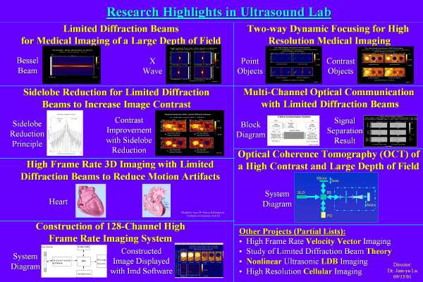
Summary:
Major projects are summarized in the following one slide. Please click the figure to view a full sized image (to be updated).
![]() (click image above to enlarge)
(click image above to enlarge)
Additional information can be obtained from Dr. Jian-yu Lu or by sending an email to: jian-yu.lu@ieee.org. Other projects such as new techniques for blood flow imaging can be found in recent publications. (See PDF-Publications for details.)
Laboratory Personnel
The Ultrasound Laboratory is currently consists of the director, Dr. Jian-yu Lu (jian-yu.lu@ieee.org), who is an expert in the field of medical ultrasound research and imaging technology. Other members who are currently working in the Ultrasound Lab including: (1) Postdocs, (2) Electrical Engineers, (3) Ph.D. students, (4) M.S. students, and (5) and B.S. students. These individuals are working on various projects related to either theory or imaging system development.
In Summary, the laboratory personnel are working on a wide range of projects including theoretical development of limited-diffraction beams, 3D ultrasound imaging, optical imaging, and analog and digital circuit designs and constructions.
Postdoc and Ph.D. Candidate (Research Assistant) Positions Open
Home Contact the webmaster, Dr. Jian-yu Lu, for questions. © Copyright 2000-Present, All rights reserved.